Tape Casting
One of the most well-known and used method to manufacture multilayered ceramic components is the doctor blade tape casting technique. Glenn N. Howatt is regarded as the godfather of tape casting and established this processing method in 1947[1] and also filed the first patent in 1948[2]. A plentiful variety of electronic components like multilayer ceramic capacitors (MLCC), actuators (MLA), varistors (MLV) or tapes for low/high temperature cofired ceramics (LTCC, HTCC) can be manufactured.
Contents
Components of a tape caster
Tape casting machine
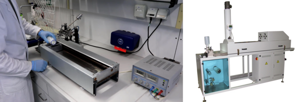
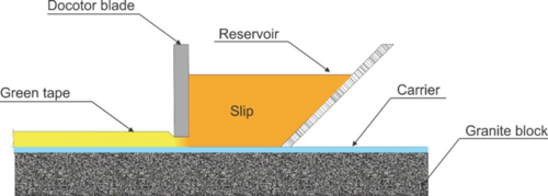
Tape casting machines are available in different scales. Usually big industrial companies have continuous tape casters with a length of up to several hundred meters. However, in academic research much smaller lab-scale tape casters are used which can range from half a meter to several meters in length. Major components of such machines are a solid and level casting surface, reservoir for the slip, doctor blade systems, drying chamber with measures for controlling the airflow and temperature of the air during drying, an adjustable speed drive control during casting, and underbed heating systems. Underbed heating systems and drying chambers are optional; however, both are useful measures to control variables during drying. The ingredients of the slip need to be adjusted towards elevated temperatures to avoid rapid drying and bubbling. Solvents may evaporate much faster thereby degrading the green tape severely. It is recommended to use temperatures close to room temperature. Continuous as well as discontinuous tapes can be prepared with lab-scale tape casters. For continuous tapes, guide rollers, and rollers with the carrier substrate are needed. If discontinuous tapes are produced, carrier substrate sheets can be used likewise.

Carrier substrate
Stainless steel belts as carrier substrates are most common in continuous manufacturing operations. It is economic and cost-effective. However, Mylar, PTFE (Teflon), cellophane, silicone-coated polyester, and many other materials are suitable as well. Especially for lab-scales, Mylar sheets are easy to handle. The binder, solvent, and plasticizer system determines the interaction with the carrier material. The slip needs to wet the surface sufficiently and after drying the green tape needs to be peeled off easily.
Reservoir
A reservoir is utilized to store the slip temporarily in front of the doctor blade. It distributes the slip along the blade and feeds the blade continuously. For lab-scale tape casters in particular, removable reservoirs with fixed gap doctor blades are used. Not only the shape of the reservoir but also the reservoir depth and viscosity of the slip have a huge impact on the cast tape. Removable reservoirs have the advantage to be cleaned easily.
Doctor blade
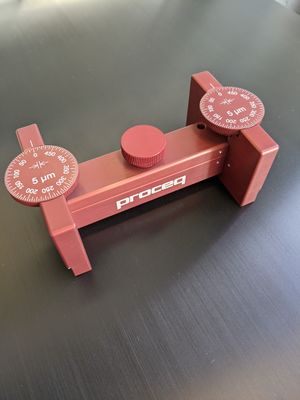
Most commonly, doctor blades are made of stainless steel or hardened carbon steel. The casting surface essentially has to be flat and smooth. Also, the doctor blades should be designed in a way that it can be disassembled for cleaning purposes. Doctor blades are mainly used for thick-film tapes, i.e. larger than 25 µm after drying. Therefore, the doctor blade gap or gap height is usually in the range of 100-1000 µm. In most laboratory operations, the blade height is adjustable and not fixed.
Feeler gauges are a helpful tool to check the set doctor blade height.
Drying chamber
Drying chambers are not necessary to cast tapes. They, nevertheless, come with lots of benefits for the process. First of all, the drying process can be controlled by keeping a constant drying rate of the slip. Choosing the right amount of air flow is equally important as retaining a steady temperature. The drying rate is highly dependent on the ingredients of the slip. The vapor pressure of solvents highly impact the drying behavior of the fluid film after casting. Another advantage that comes along a drying chamber is keeping dirt and dust away from the tape. Especially for small lab-scale tape casters drying chamber are not always available or has to be custom-made.
Process of tape casting
Slip delivery
After mixing the slip system, air can be trapped within the slip. To remove remaining air bubbles and promote smooth and homogeneous green tapes without defects, a de-airing step is required. Putting the slip under vacuum will help to remove air. It needs to be noted that too high vacuum tends to let evaporate solvent. This will unbalance the weight ratios of the slip and change its rheological behavior. Subsequent to de-airing the slip will be poured into the reservoir of the machine. Additional sieves can be used to prevent e.g. milling balls from falling into the reservoir. Before starting to cast the slip is supposed to be distributed in the reservoir. Furthermore, the sedimentation behavior will have an effect. Also, if the slip system is well-dispersed, sedimentation can take place after a certain amount of time. This will influence the starting point of the final tape and deteriorate the homogeneity of it.
Casting
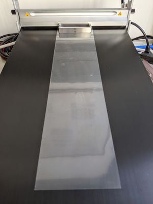
The doctor-blade gap defines the wet thickness of the tape being cast. The casting speed is supposed to be set in the range of 0.7 - 1 m/min but should be adjusted according to the viscosity of the slip. Depending on the scale of the casting device either starting the wiping doctor blade across the fixed carrier substrate or starting the carrier underneath the stationary blade follows. The process itself is rather easy and fast. The crux is to form a homogeneous and uniform tape without defects. Up to here, variables such as rheological behavior, viscosity, slip surface tension, wetting behavior, reservoir height, doctor blade height and shape, and casting speed among others were shortly mentioned.
Drying
The tape drying process is somewhat unique since it is a one-side drying process. The solvent is removed from the upper side of the cast. Therefore, the solvents have to diffuse through the tape and evaporate on the upper surface. Depending on the stability of the slip, sedimentation of solid ceramic particles and organic ingredients will be initiated. A higher porosity in the tape enhances the drying speed but is adverse to final properties of the component. A so-called skin retarder, for instance methyl ethyl ketone (MEK), can aid solvent migration speed by forming a skin on the surface which retards evaporation and providing a liquid pathway from bottom to surface, too. In general, the vapor pressure of solvents will have a huge influence on the drying behavior. The so-called orange peel can be observed when the top layer is drying much faster than the bottom layer of the tape and will be discussed in the following section.
Tape characterization
In this section, a selection of defects and hands-on techniques to gauge the quality of the tapes are given.
- The quality of the cast tape can be checked with rather easy measures. A light transmission analysis (LTA) compares the light transmission in different regions of the tape. It helps to identify streaks, cracks, bubbles, dust, wrinkles, non-uniform thicknesses, and agglomerates. A perfect tape would be completely uniform and light is transmitted equally. However, any inhomogeneity disturbs the transmission of light. Alternatively, this can also be performed by utilizing the human eye as the detector.
- The green tape thickness and its flatness/uniformity is probably the most vital characteristic to be evaluated. Various instruments are available to measure the thickness of the tape. Nevertheless, a micrometer with flat faces is supposed to be the most appropriate device. Tips and faces of some calipers or micrometers have rounded or sharp tips and are inappropriate due to too high pressures.
- Determining the green oxide-only density is another key parameter. Enough shrinkage and high fired densities can only be achieved when ceramic particles are in proximity already in the green state but especially after the binder burnout. This density is calculated by the mass of ceramic powder per unit volume while organics and volatile ingredients are not taken into account. This is necessary because after binder burnout usually only the brittle and rigid ceramic network within the pre-defined volume is left.
- Streaks and grooves on the surface can be spotted, too. If streaks are continuing all over the tape, proper cleaning of the doctor blades is the best choice. If streaks or grooves occur rather sectionally, bigger ceramic agglomerates may be trapped for a certain amount of time below the blade. Decent dispersion of the ceramic particles in the slip and the right amount of dispersant are one of the approaches to eliminate these types of defects.
- Several other defects can occur during drying. For instance, wrinkling, mud flat cracking, or the so-called orange peel can be detected. Here, the surface of the dried tape resembles the skin of an orange and leaves back small craters on the surface. The mechanisms causing those three types of defects are likely the same but they all can be prevented. Independent on wrinkling, cracking, or craters being formed, the top surface drying has to be decelerated. More liquid diffusion from the bottom of the tape is necessary to compensate the evaporation of solvent on the surface. Utilizing skin-retarders or adjusting air flow as well as temperatures help to prevent those defects during drying.
- Another emerging defect is center cracking. The crack is not always located in the center but tend to nucleate at inhomogeneities like bubbles or agglomerates and propagates along the casting direction of the tape. Slowing down the drying rate, similar to the defects before, prolongs liquid motion and a higher amount of solvent can leave the slip prior to gelation. Another effective way to impede this issue is to increase the binder content which builds up the network in the green tape. The adhesion of the slip/tape has to be higher than the adhesion of the carrier substrate.
- A last example is specifying the green tape's tensile strength. The dried tapes have to be further processed and, therefore, need to exhibit a certain yield strength. Most often this is empirically derived since it is tedious to properly measure it. Binder and plasticizer content manipulate the green tensile strength. A balance needs to be found between processability and green sheet density.
References
- ↑ [1] Howatt, G.N., Breckenridge, R.G. and Brownlow, J.M. (1947), FABRICATION OF THIN CERAMIC SHEETS FOR CAPACITORS. Journal of the American Ceramic Society, 30: 237-242.
- ↑ [2] Howatt, G.N., Method of Producing High Dielectric High Insulation Ceramic Plates, U.S. Patent 2,582,993 (filed October 29, 1948).
- ↑ [3] Webpage KEKO equipment d.o.o. Laboratory Tape Casters L-Series, accessed: October 29, 2022


